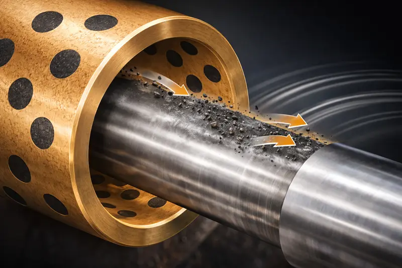
Are you buying graphite plugged bushings just based on whether they have graphite? This common mistake overlooks the real factor determining performance, leading to unexpected equipment failures and downtime.
The layout of the graphite plugs, not just their presence, is what dictates lubrication effectiveness.[^1] A proper layout creates a continuous lubricating film over the entire friction surface. An improper one leads to dry spots, accelerated wear, and premature failure of the bushing and shaft.
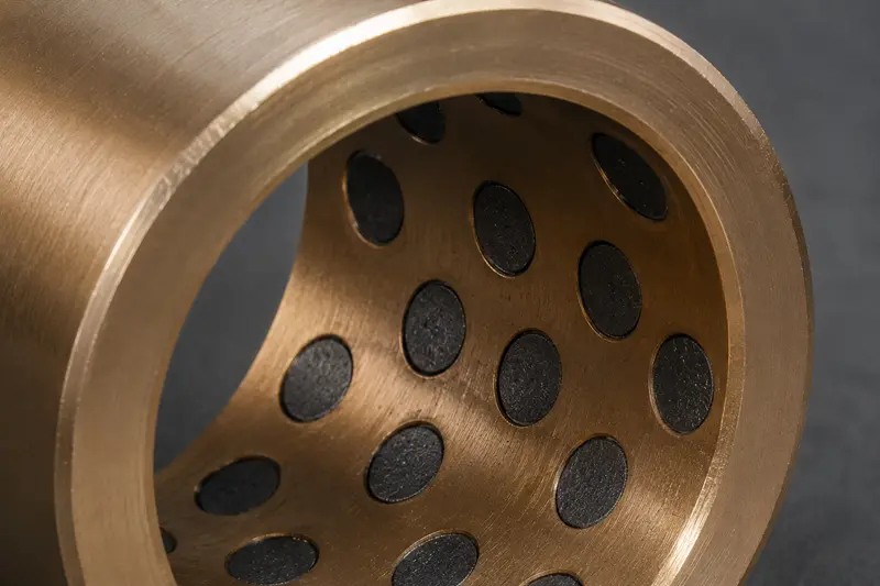
Many of my customers who are sourcing parts see graphite plugs and think, "Great, it's self-lubricating." But from our perspective as a factory, that's only half the story. The real engineering is in where those plugs are placed. A poor layout is like having a fire extinguisher you can't reach when a fire starts.[^2] The potential is there, but it's useless in practice. The layout isn't just for looks; it's a carefully designed lubrication system. Let's break down what really matters.
Does More Graphite Always Mean Better Lubrication?
You might think that packing a bushing with as much graphite as possible is the best strategy. But this can actually weaken the part, especially under heavy loads.
No, more graphite is not always better. The key is balance. Too little graphite provides insufficient lubrication, while too much weakens the bronze base's structural strength.[^3] The ideal graphite coverage area provides enough lubricant without compromising the bushing's ability to carry the load.
When we design a graphite plugged bushing, we start with the application's load requirements. The bronze alloy base is what carries the weight. The graphite's job is to release a solid lubricating film during movement to reduce friction.[^4] If you have too much graphite, you have less bronze, which reduces the bushing's load-carrying capacity. This is a critical failure point in high-load applications like construction equipment pivots. We often see bushings fail not from lack of lubrication, but because the base structure collapses. The goal is to find the sweet spot.[^5] As a general rule, the graphite coverage area is typically between 25% and 30% of the friction surface.
Here's how we think about it:
| Load Condition | Graphite Coverage | Rationale |
|---|---|---|
| High Load, Low Speed | Lower (e.g., 25%) | The primary need is structural strength from the bronze base to prevent deformation. |
| Medium Load, Medium Speed | Standard (e.g., 25-30%) | A balanced approach for both strength and consistent lubrication. |
| Low Load, High Speed | Higher (e.g., 30%+) | Strength is less critical, so more graphite can be used to ensure a stable film at higher speeds. |
Ultimately, the layout is an engineering calculation, not a guess. We adjust the percentage based on the forces at play to ensure the bushing is both strong and well-lubricated.
Why Does the Pattern of Graphite Plugs Matter So Much?
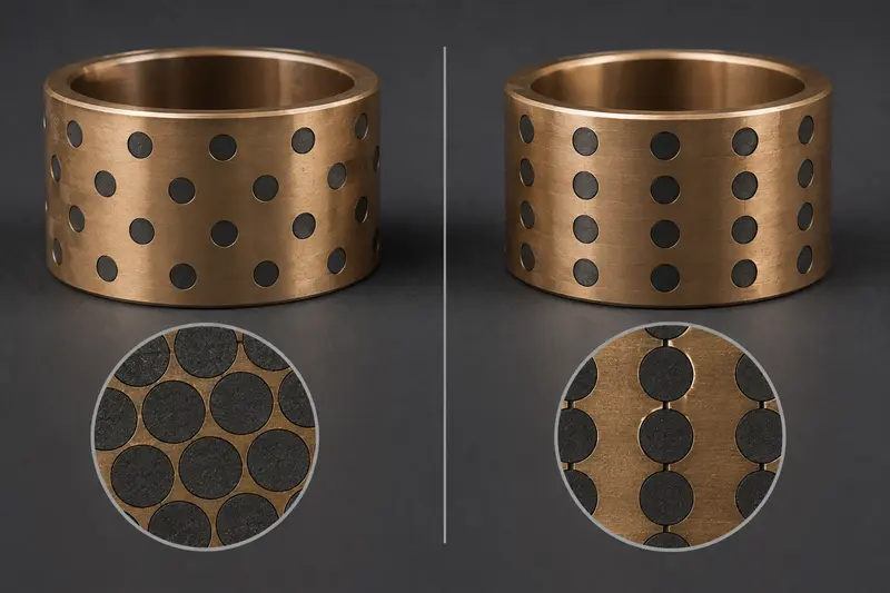
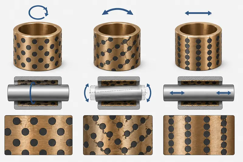
You've probably seen bushings with plugs in straight lines, while others have them in a diamond or spiral pattern. This isn't random. A bad pattern creates "dead zones" without lubrication.
The pattern ensures the moving shaft is always in contact with a graphite plug. A staggered or intersecting pattern creates a continuous lubrication path, preventing any part of the shaft from running dry.[^6] A simple linear pattern can leave large areas unlubricated, causing uneven wear.
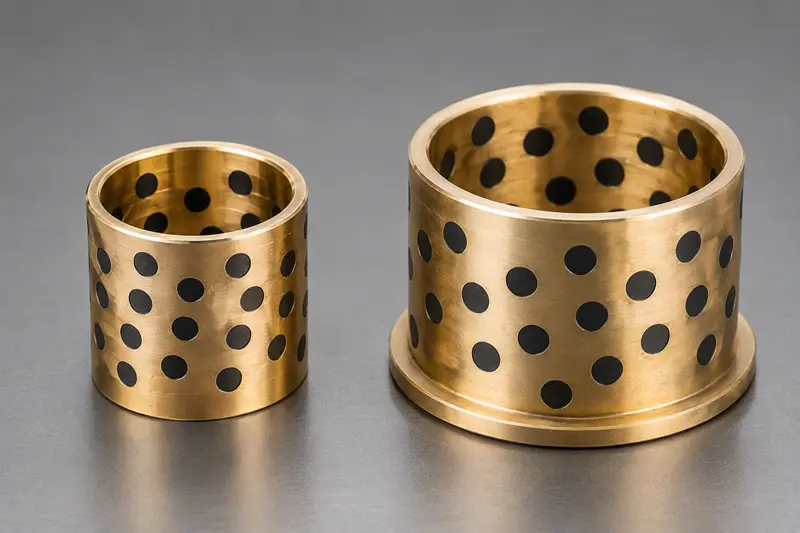
Think about painting a wall with a small roller. You wouldn't just make one vertical stripe and call it done. You'd overlap your strokes to ensure the entire wall is covered. The same principle applies to lubricating a shaft. The goal of the plug pattern is to make sure that as the shaft moves, it continuously picks up graphite particles and spreads them into a complete film. A staggered, diamond, or spiral pattern is excellent for this, especially in rotating applications. As the shaft turns, it crosses over different plugs, constantly replenishing the lubricating film across its entire surface. In contrast, if the plugs are just in a few straight lines, the areas between those lines might never get properly lubricated, leading to metal-on-metal contact and scoring.
| Pattern Type | Best For | Why It Works |
|---|---|---|
| Staggered / Diamond | Rotation, General Use | Ensures the shaft always crosses a plug, providing continuous film formation. |
| Linear / Rows | Pure Linear Motion | Aligns with the direction of movement for consistent lubrication along a straight path. |
| Circular / Arc | Oscillation / Pivoting | Concentrates graphite in the specific, limited arc of motion. |
When a client sends us a drawing, the plug pattern is one of the first things we analyze. We check if it matches the intended motion to prevent future problems.
Should Bushings for Rotating and Sliding Motions Have the Same Layout?
It’s easy to assume one bushing design fits all movements. But a layout designed for full rotation will fail miserably in a short, back-and-forth oscillating motion.
Absolutely not. The graphite plug layout must be optimized for the specific type of motion: rotation, oscillation, or linear sliding.[^7] Each movement creates a unique friction path, and the plugs must be positioned along that path to provide continuous lubrication where it's needed most.
I once worked with a customer whose new machine was failing within weeks. The bushings were showing extreme wear in one specific spot. After checking their design, I saw the problem immediately. They were using a standard, evenly spaced graphite bushing in an application with a very small oscillating angle—only about 15 degrees. The shaft was moving back and forth over an area that had no graphite plugs at all. It was a classic case of dry friction. We redesigned the bushing to concentrate the graphite plugs only within that 15-degree arc of movement. The problem disappeared. This is why understanding the motion is non-negotiable.
Here’s a breakdown of how we approach it:
- Full Rotation: For a shaft spinning 360 degrees, a staggered or spiral pattern is ideal. This ensures the entire circumference of the shaft is continuously lubricated as it turns.
- Oscillation (Pivoting): This is the trickiest. The movement is limited to a specific angle. The graphite plugs must be placed within this working arc. Placing them anywhere else is a waste and leaves the critical area unprotected.
- Linear Motion (Sliding): For parts that slide back and forth, the plugs should be arranged in rows that align with the direction of travel. This creates lubricated "runways" for the sliding component.
The motion type is a fundamental input for our design process.[^8] It tells us exactly where the friction will happen, so we know where to put the lubricant.
How Does Load Direction Change Where Graphite Plugs Should Go?
Many people think plugs should be spread evenly for balance. But this can weaken the bushing right where it needs to be strongest, in the main load-bearing area.
If a load is consistently applied from one direction, the layout must be strategic. Plugs should be placed around the load zone to provide lubrication, but kept away from the point of peak pressure.[^9] This preserves the bronze's strength to prevent deformation under heavy force.
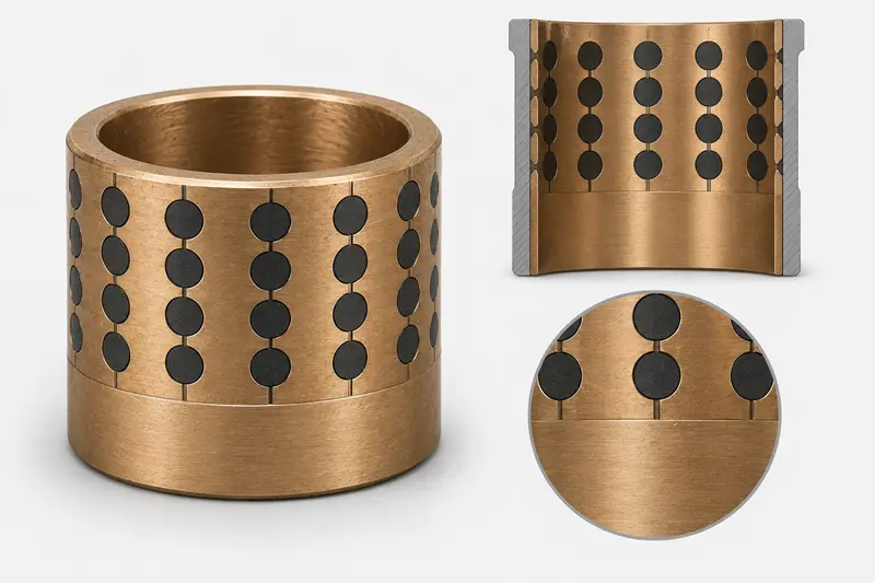
Imagine a heavy-duty axle on a piece of farm equipment. Gravity and the machine's weight create a constant downward force. This means the pressure isn't spread evenly around the bushing; it's concentrated on the bottom surface. If we were to drill graphite holes uniformly, we would be removing critical bronze material from this high-pressure zone. This could cause the bushing to deform or crack under peak load. The correct approach is what we call a load-optimized layout. We keep the area of maximum pressure (often a 60 to 90-degree arc at the bottom) as solid bronze for maximum strength. Then, we place the graphite plugs on either side of this zone. As the shaft rotates, it picks up lubricant from the sides and drags it through the high-pressure zone, providing lubrication without compromising structural integrity.
| Layout Approach | Pros | Cons |
|---|---|---|
| Uniform Layout | Simple to manufacture, looks balanced. | Weakens the main load zone, can lead to deformation under high, directional loads. |
| Load-Optimized Layout | Maximizes strength in the pressure area, prevents collapse. | Requires analysis of load direction, slightly more complex design. |
For any B2B buyer in OEM or heavy industry, asking about the load zone is a sign of a quality supplier. It shows we're thinking about long-term performance, not just making a part that looks correct.
Can You Put Any Graphite Pattern on Any Bushing?
A customer might request a dense graphite pattern on a small, thin-walled bushing. But this is often physically impossible and can cause the part to fail before it's even used.
No, a bushing's size and especially its wall thickness place firm limits on the graphite layout. Drilling too many or too-large holes into a thin wall severely compromises its structural integrity, making it prone to cracking during manufacturing or under operational load.
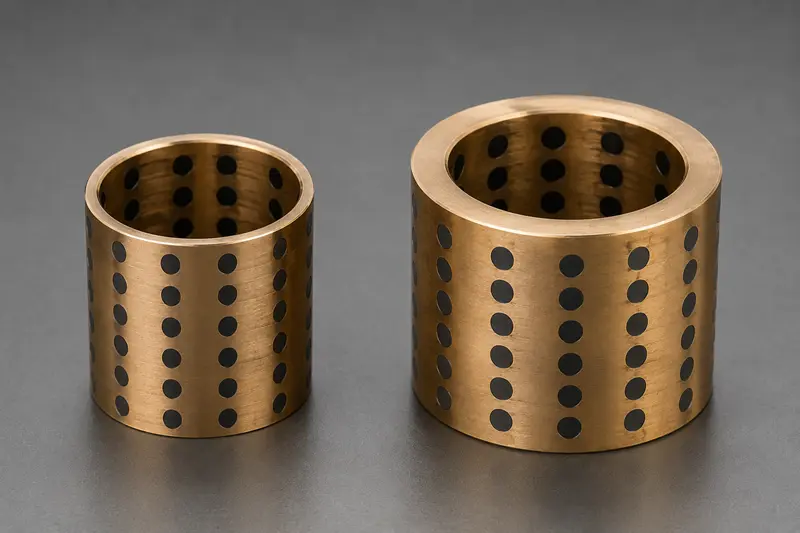
We see this request from time to time, and it's our job as the manufacturer to explain the physical limitations. Every hole we drill for a graphite plug removes material and creates a point of stress. On a bushing with a thick wall, this isn't a problem because there's plenty of surrounding bronze to maintain strength. But on a thin-walled bushing, there's very little material to begin with. Overly aggressive drilling can cause the bushing to lose its roundness, crack during press-fitting, or simply collapse under load. As a factory rule, we have strict guidelines for the ratio between plug diameter and wall thickness.
For example, a common guideline is:
This ensures there is enough structural material left around each plug to maintain the bushing's overall integrity.
| Wall Thickness | Feasibility of Dense Pattern | Risk Factor |
|---|---|---|
| Thick Wall (>5mm) | High | Low risk of distortion or cracking. |
| Medium Wall (3-5mm) | Moderate | Layout must be carefully designed to balance coverage and strength. |
| Thin Wall (<3mm) | Low / Not Feasible | High risk of structural failure. Lighter patterns or different bearing types are recommended. |
It's a practical manufacturing constraint. We can't defy physics. Part of our role is to guide our clients toward a design that is not only effective but also manufacturable and reliable in the long run.
Conclusion
The graphite plug layout is a core part of the lubrication system design. A successful layout perfectly balances lubrication coverage with the structural strength of the bronze base.
[^1]: "[PDF] Lubrication & Cooling Systems - FAA", https://www.faa.gov/sites/faa.gov/files/08_amtp_ch6.pdf. This source explains how the arrangement of graphite plugs impacts lubrication efficiency in bushings. Evidence role: mechanism; source type: education. Supports: The layout of graphite plugs determines lubrication effectiveness.. [^2]: "Automated Lubrication - Benefits and Design Options", https://www.machinerylubrication.com/Read/175/automated-lubrication. This source uses an analogy to explain the importance of accessible lubrication in bushings. Evidence role: general_support; source type: other. Supports: A poor layout of graphite plugs leads to ineffective lubrication, similar to inaccessible tools during emergencies.. Scope note: The analogy is illustrative but does not provide direct evidence for the claim. [^3]: "Materials science - Wikipedia", https://en.wikipedia.org/wiki/Materials_science. This source discusses the trade-offs between graphite coverage and structural integrity in bronze bushings. Evidence role: mechanism; source type: research. Supports: Excessive graphite weakens the bronze base, while insufficient graphite reduces lubrication.. [^4]: "[PDF] Solid lubricant materials for high temperatures - a review", https://ntrs.nasa.gov/api/citations/19890015265/downloads/19890015265.pdf. This source explains the role of graphite in forming a lubricating film in bushings. Evidence role: mechanism; source type: education. Supports: Graphite releases a solid lubricating film during movement to reduce friction in bushings.. [^5]: "Shape Optimization of Rubber Bushing Using Differential Evolution ...", https://pmc.ncbi.nlm.nih.gov/articles/PMC4168157/. This source discusses the balance between lubrication and structural strength in bushings. Evidence role: mechanism; source type: research. Supports: Finding the balance between lubrication and structural strength is critical in bushing design.. Scope note: The concept of a 'sweet spot' may vary based on application specifics. [^6]: "Optimize Lubrication Effectiveness for Success in 2026 - Reliable", https://reliamag.com/articles/overall-lubrication-effectiveness-ole/. This source explains how staggered or intersecting plug patterns ensure continuous lubrication in bushings. Evidence role: mechanism; source type: education. Supports: Staggered or intersecting plug patterns prevent dry spots and ensure continuous lubrication.. [^7]: "[PDF] Stress Aware Layout Optimization - David Blaauw", http://blaauw.engin.umich.edu/wp-content/uploads/sites/342/2017/11/358.pdf. This source discusses how motion type influences graphite plug layout in bushings. Evidence role: mechanism; source type: research. Supports: Graphite plug layout must be optimized for specific motion types like rotation, oscillation, or sliding.. [^8]: "Essential Components for Mechanical Engineers - Five Flute", https://www.fiveflute.com/guide/bearings-and-bushings-essential-components-for-mechanical-engineers/. This source explains how motion type influences the design process for bushings. Evidence role: mechanism; source type: education. Supports: Motion type is a fundamental factor in designing graphite plug layouts for bushings.. [^9]: "Plug & Process Loads - Better Buildings Solution Center", https://betterbuildingssolutioncenter.energy.gov/plug-process-loads. This source explains the importance of strategic plug placement around load zones in bushings. Evidence role: mechanism; source type: education. Supports: Graphite plugs should be placed around load zones but not at peak pressure points to preserve strength.. [^10]: "Wall Plug Drill Sizes: Chart and Guide | Fastbuild Supplies", https://www.fastbuildsupplies.co.uk/knowledge-hub/wall-plug-drill-sizes-chart-guide. This source provides guidelines for the ratio between wall thickness and plug diameter in bushings. Evidence role: statistic; source type: institution. Supports: Wall thickness should be at least 1.5x to 2x the plug diameter to maintain structural integrity.. Scope note: Guidelines may vary based on specific materials and applications.